

Best Closed-Type Goggle Valve Selection for Industrial Needs
2026-07-11
Selecting the right closed-type goggle valve can make or break your industrial process—one wrong choice, and you’re looking at costly downtime or safety risks. Yet with so many options on the market, it’s easy to get lost in specs that sound identical. At THT, we’ve seen firsthand how a well-matched valve streamlines operations, while a generic pick leads to headaches. In this guide, we cut through the noise to help you pinpoint the valve that fits your exact needs—without the guesswork.
Understanding Closed-Type Goggle Valves and Their Industrial Role
Closed-type goggle valves are a specialized form of isolation valve designed for applications where absolute shutoff is critical. Unlike conventional gate or ball valves, they feature a rotating spectacle plate—often shaped like a pair of spectacles—that physically blocks the flow path when closed. One side of the plate is solid, acting as a blind, while the other side has an opening that allows full flow when aligned. The “closed-type” designation indicates that the mechanism and moving parts are fully enclosed within a robust housing, protecting them from external contaminants and ensuring reliable operation in harsh environments.
In industrial settings, these valves are valued for their simplicity and fail-safe characteristics. They provide a visible, unambiguous indication of position: the plate’s orientation clearly shows whether the line is open or sealed. Maintenance teams often prefer them in lines handling abrasive slurries, corrosive chemicals, or hot gases, where standard valves might leak or degrade quickly. By combining a tight shutoff with a compact, flanged design, closed-type goggle valves minimize fugitive emissions and help plants meet stringent safety and environmental regulations without the complexity of double block and bleed systems.
Typical installations include tank farms, reactor isolation, and transfer line diversion in petrochemical refining, mining, and power generation. They excel where lines must be periodically cleared or where a guaranteed no-flow condition is required during maintenance. The enclosed construction also reduces the risk of personnel injury from moving components and shields the sealing surfaces from debris, extending service life. Despite their niche, these valves remain a practical choice whenever system integrity depends on a visible, mechanically locked separation between process streams.
Key Features That Define a Reliable Goggle Valve
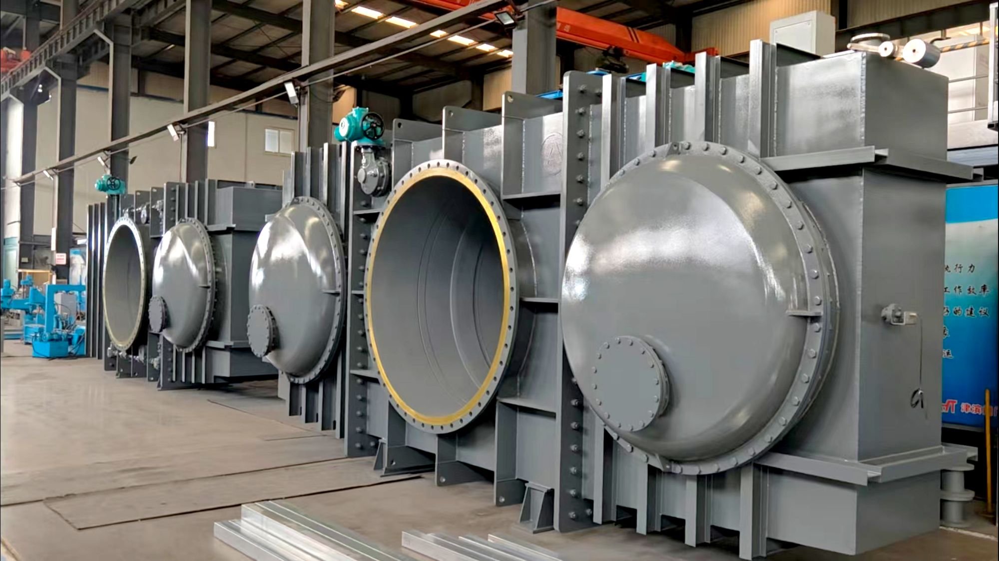
In industrial processes where absolute shut-off is non-negotiable, the goggle valve stands out as a trusted safety device. Its defining characteristic lies in a simple, robust design: a hefty spectacle plate that swings or slides into position, physically blocking the line of sight. Unlike traditional valves that rely on sealing surfaces that can wear or leak, a reliable goggle valve ensures complete isolation by presenting an impermeable metal barrier. This means zero cross-contamination and absolute protection for downstream equipment and personnel during maintenance.
True durability in a goggle valve comes from its construction. Look beyond the standard and demand heavy-duty materials that can withstand thermal cycling, corrosive media, and mechanical stress. The sealing faces should be precision-machined to ensure a perfect mate with the flange, while the operating mechanism—whether manual, chainwheel, or actuated—must deliver smooth, jam-free movement even after years of idleness in harsh environments. A well-engineered goggle valve also features clear visual position indicators that leave no room for guesswork: an unmistakable open or closed sign that can be seen from a distance, enhancing plant safety at a glance.
The mark of a truly reliable goggle valve is its ability to perform flawlessly when called upon, often in emergency situations. It should require minimal force to operate, even under differential pressure conditions, and incorporate safety interlocks to prevent inadvertent operation. Maintenance should be straightforward, with easy access to wearing parts and a design that simplifies replacement of soft goods. In essence, a dependable goggle valve combines brute isolation strength with thoughtful engineering details—so that when the moment comes, it delivers an uncompromising seal without drama or delay.
Material Choices for Harsh Operating Environments
Selecting materials that can withstand extreme temperatures, corrosive chemicals, and mechanical stress demands more than just picking a familiar alloy or polymer. In applications ranging from deep-sea oil extraction to aerospace engines, the margin for error is razor-thin. Engineers must weigh not only the immediate performance requirements but also long-term factors like creep resistance, fatigue life, and thermal expansion mismatches that can silently degrade components over time. Too often, off-the-shelf solutions fail because they were never designed to handle the layered challenges of a truly harsh environment.
Ceramics and composites have carved out a critical niche where metals falter. For instance, silicon carbide and alumina excel in high-temperature, abrasive settings, maintaining structural integrity when superalloys begin to soften. Meanwhile, carbon-fiber-reinforced polymers offer a unique strength-to-weight ratio that resists both corrosion and fatigue, making them invaluable for offshore structures or chemical processing equipment. The key is understanding that no single material is a silver bullet—hybrid assemblies that pair a tough core with a specialized coating often outperform monolithic alternatives, especially when thermal cycling or galvanic corrosion comes into play.
Cost invariably enters the equation, but it should be viewed through a life-cycle lens. Cheaper stainless steels might survive a laboratory test, yet they can catastrophically fail halfway through their expected service life if trace impurities in the environment trigger stress corrosion cracking. Investing in a premium nickel-based alloy or a bonded metallic-ceramic component often yields lower total costs when you account for downtime, replacement labor, and safety risks. Ultimately, the right material choice is not the one that simply endures a given condition on paper—it is the one that stays predictable and stable under the messy, combined stresses of real-world operation.
Sizing and Pressure Considerations for Optimal Flow Control
Getting the pipe and valve sizes right isn’t just about matching numbers—it’s about understanding how the entire system breathes under pressure. When lines are undersized, velocity spikes can cause noise, erosion, and unpredictable pressure drops that throw off control loops. Oversizing, on the other hand, often leads to poor rangeability, forcing valves to operate near their seats where precision goes out the window. The goal is to find that sweet spot where the pressure drop across the valve is large enough to give it authority over the system, yet not so large that it wastes energy or invites cavitation.
Pressure dynamics shift the moment a valve starts to open, and those shifts aren’t always linear. A control valve’s inherent characteristic rarely matches its installed behavior if you ignore the pipeline’s frictional losses and elevation changes. That’s why sizing calculations need to go beyond simple Cv formulas—they should account for the actual pressure differential at the maximum and minimum flow conditions you expect. If the process demands a wide turndown, you might need to step back and reconsider the trim style or even split the duty between two valves to keep control accurate without sacrificing stability.
Material selection and thermal effects play a quieter but equally critical role. Pressure ratings can degrade at elevated temperatures, and a valve body that’s perfectly sized at ambient conditions might become a bottleneck when thermal expansion reduces the clearances. Similarly, flashing or outgassing in liquid lines can turn a well-calculated Cv into a wild guess. The best installations come from pairing the sizing data with a realistic view of the process’s full operating envelope—not just the design point. That means questioning assumptions about upstream pressure variability and thinking about what happens when the plant runs at turndown, startup, or during unexpected transients.
Maintenance Practices That Extend Valve Lifespan
A valve's longevity isn't just about the initial build quality—it's largely shaped by how well it's looked after day to day. One of the simplest yet most overlooked habits is keeping the valve and its surrounding area clean. Dirt, debris, or solidified process fluid around the stem or seat can cause scoring every time the valve cycles. A quick wipe-down during routine rounds, especially on stem threads and bonnet joints, prevents abrasive particles from working their way into soft seals and packing. This small step often means the difference between a valve that seats tightly for years and one that starts leaking prematurely.
Lubrication is another area where consistency trumps volume. Valve stems, thrust bearings, and gear operators all rely on a thin film of grease to handle repeated torque without galling. But too much lubricant attracts contaminants; too little invites corrosion. The goal is to use the manufacturer’s specified product at a frequency that matches the valve’s duty cycle—high-cycle automated valves might need a touch-up every few thousand strokes, while manually operated isolation valves can go months between applications. Pay special attention to buried or insulated valves, where moisture often gets trapped and accelerates stem corrosion under the lagging.
Even with perfect housekeeping, valves have wear parts that need periodic adjustment. Packing gland followers, for instance, should be snugged down just enough to stop a weep—overtightening only crushes the packing and makes the valve harder to turn, leading operators to force it. Likewise, checking torque on body-bonnet bolting after thermal cycles can prevent blowout gasket failures. Finally, don't treat all valves alike: compare the actual service conditions against the original datasheet. A valve handling a new product, higher temperature, or faster cycling than it was spec'd for will degrade quickly unless you adjust the maintenance frequency to match the real-world demand.
Making the Right Choice for Your Specific Application
Every environment places its own demands on equipment—what works perfectly in a climate-controlled lab might struggle on a dusty factory floor. Instead of chasing the highest specs, start by mapping out the real-world conditions your solution will face. Temperature swings, vibration, moisture, and even the skill level of the people using it day to day can matter more than raw performance on paper. Paying attention to these practical factors early on can save a lot of headaches later.
It's also worth looking beyond the initial purchase and considering how the choice will age with your needs. Think about maintenance requirements, availability of spare parts, and whether the technology can adapt if your application evolves. Sometimes a slightly less advanced but well-supported option ends up being the smarter bet because it keeps downtime low and doesn't require specialized expertise to keep running. Run through a few realistic scenarios—not just perfect conditions—to see how each candidate holds up.
Finally, don't underestimate the value of hands-on trials and feedback from those who have already tackled similar challenges. Demos and datasheets rarely tell the whole story. Try to test the most critical functions in your own workflow, and listen carefully to what the people actually operating the gear have to say. Their intuition about what feels right—or what's going to be a constant annoyance—often points you toward the choice that will truly deliver over the long haul.
FAQ
A closed-type goggle valve offers a compact, leak‐proof shutoff that physically separates media without the hassle of swinging blinds or dealing with heavy spades. Its enclosed body protects the spectacle plate from atmospheric contamination, making it ideal for harsh outdoor installations where debris or moisture could compromise an open design.
You’ll find them most appreciated in oil refineries, petrochemical plants, and gas processing facilities. Anywhere that demands absolute isolation during maintenance—think flare lines, thermal oxidizers, or reactor bypasses—the closed-type goggle shines because it prevents even minute cross-contamination or fugitive emissions.
Match the valve flange standard to your piping spec first—ASME B16.5 for most. Then look at your operating pressure and temperature to pick a class that gives you a comfortable margin above max operating limits. Don’t just size for pipe diameter; consider flow velocity and potential slurry buildup if you’re dealing with dirty service.
Absolutely. While CF8M stainless is common, harsh media might demand Hastelloy internals or fused-in corrosion resistant liners. Carbon steel bodies with electroless nickel coating can handle sour services at a lower cost. The spectacle plate itself can be a different material from the body for optimized cost-performance.
The sealed bonnet completely boxes in the spectacle plate, so it won’t collect rainwater or windblown grit. This keeps the sealing surfaces pristine and eliminates the rusted plates and stuck mechanisms you often see with open-slot designs. Plus, the enclosed body catches any sudden pressure pulse instead of blowing gaskets outward.
Yes, and it’s a major advantage in dangerous locations. You can get them with pneumatic or electric actuators that rotate the spectacle plate from a control room. Look for models with a locking mechanism and position indicators that confirm ‘open’ or ‘shut’ without sending someone into a risk zone just to verify.
Far less labor. Instead of unbolting flanges and maneuvering a heavy blind, a single operator can stroke the valve in minutes. You’ll typically just need to lubricate the stem and inspect the gaskets annually. Some designs even allow in‐line replacement of the spectacle plate without pulling the valve body, slashing downtime.
Conclusion
Selecting the best closed-type goggle valve isn't just about picking a component off a shelf—it's about understanding how these workhorse devices maintain absolute isolation in demanding industrial settings. Unlike standard valves, a closed-type goggle valve physically separates pipeline sections with a blind plate, making it indispensable in applications where zero leakage is non-negotiable, such as in chemical transfer lines or fuel gas systems. What separates a truly reliable valve from the rest boils down to design nuances: a robust body that resists warping under thermal cycling, a sealing mechanism that doesn't degrade with repeated operation, and an actuator that delivers consistent, jam-free movement even after long idle periods. Material selection is equally critical; in corrosive or high-temperature environments, choosing the right alloy—whether it's Hastelloy for aggressive chemicals or stainless steel with appropriate heat treatment for elevated temperatures—can mean the difference between years of trouble-free service and premature failure.
Beyond material resilience, accurate sizing and pressure rating are the backbone of optimal flow control. Oversizing leads to sluggish operation and unnecessary cost, while undersizing risks choke points and dangerous pressure build-up. It's essential to match the valve's pressure class to the system's maximum operating conditions, factoring in transient spikes that often get overlooked during initial design. However, even the best-chosen valve will underperform without a thoughtful maintenance routine: regular inspection of the blind plate for pitting, lubrication of the sliding mechanism with compatible grease, and verifying gasket integrity can extend lifespan significantly and avert costly downtime. Ultimately, the right choice emerges when you align all these factors—the specific media, operating extremes, safety requirements, and life-cycle costs—with a valve that has been proven in similar applications. This holistic approach, rather than a checklist mentality, ensures that the selected closed-type goggle valve becomes a reliable, long-term asset rather than a recurring headache.
Contact Us
Contact Person: Su Zhang
Email: [email protected]
Tel/WhatsApp: +86-25219206
Website: https://www.tht-valve.com/