

Custom Ductile Iron Casting: Key Benefits and Design Considerations for Your Next Project
2026-09-17
Every project has its own set of demands, and off-the-shelf components often fall short. That's where custom ductile iron casting steps in—offering a blend of strength, durability, and design flexibility that standard parts simply can't match. But before you dive in, you need to know what makes it tick, from its impressive mechanical properties to the design rules that keep costs in check. In this guide, Zhaoyuqi breaks down the key benefits and the critical design considerations you should weigh for your next project, so you can avoid costly mistakes and get the most out of every pour.
Why Ductile Iron Handles Impact Loads That Crack Grey Iron
Grey iron's graphite flakes act like internal cracks. Under sudden load, stress concentrates at sharp flake tips, so once a crack starts it travels almost unimpeded through the brittle matrix. Ductile iron replaces those flakes with spheroidal graphite nodules. Because a sphere has no sharp edge, it does not create the same stress riser; the metal around each nodule can yield locally before any fracture can propagate.
That microstructural difference changes fracture behavior from brittle to ductile. Ductile iron absorbs impact energy through plastic deformation, while grey iron fails with almost no permanent set. The ferritic or pearlitic matrix in ductile iron can also be adjusted by heat treatment, giving engineers a range of strength and elongation combinations to match service conditions.
Field failures reflect this: grey iron compressor housings or pump bodies crack when dropped or hit, while ductile iron parts with similar wall thickness survive the same mishandling. Even after overload, ductile iron typically shows visible deformation before breaking, which is a useful warning in structural applications.
Designing Thin-Wall Sections Without Losing Tensile Strength
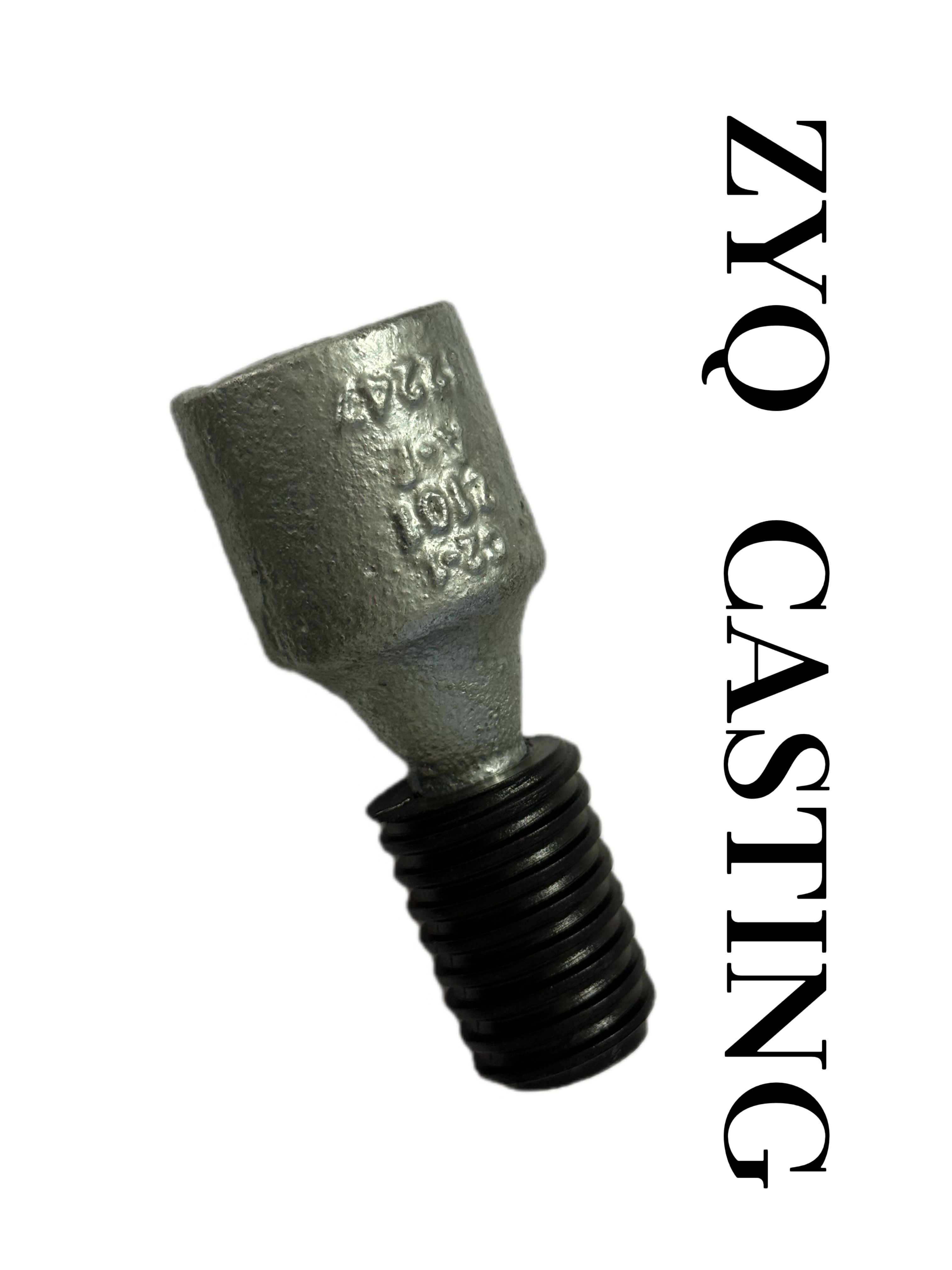
Reducing wall thickness usually invites a drop in tensile performance, but the real issue isn't the thinness itself—it's how the load path gets interrupted. Sharp internal corners, abrupt transitions, and poorly placed ribs create stress concentrations that fail long before the bulk material reaches its limit. By using generous radii at every junction and tapering sections gradually, you can keep the stress flowing smoothly through the part. This approach lets you shave weight without turning a once-strong section into a weak point.
Material choice does a lot of quiet work here. High-flow grades with narrow molecular weight distribution fill thin walls more consistently, avoiding micro-voids that act as crack starters. Pairing that with a slightly higher melt temperature and slower injection speed keeps orientation uniform, which preserves longitudinal strength even when the wall drops below two millimeters. Some molders also add a thin ribbed pattern on the non-cosmetic side—this increases section modulus without noticeably raising weight or sink marks.
Validation is where most designs fall short. A tensile test on a flat coupon won't predict how a thin-walled rib or boss behaves under load. Instead, build a simple test fixture that mimics the actual load direction and pull rate, then compare thick and thin versions side by side. Often the thin design holds up if the geometry is clean and the fill is uniform; the failure comes from over-reliance on nominal wall thickness as a strength indicator rather than looking at stress distribution across the entire feature.
Near-Net-Shape Casting: Cutting Machining Time and Material Waste
Near-net-shape casting eliminates much of the rough machining typically required after conventional casting. By producing components with tighter dimensional tolerances and better surface finish, foundries can deliver parts that go straight to finish machining or even direct assembly. This approach reduces cycle times on CNC machines, lowers tool wear, and frees up production capacity for higher-value work.
Material waste drops significantly because less excess stock is left on the casting. Traditional methods often require several millimeters of extra material to accommodate shrinkage and distortion, but near-net-shape processes control solidification more precisely. The result is a leaner use of alloys—especially important for expensive metals like titanium or nickel-based superalloys—and less scrap that must be recycled or discarded.
In practice, engineers achieve these gains through techniques such as investment casting, squeeze casting, or semi-solid metal processing, each tailored to specific part geometries and production volumes. The initial tooling may cost more, but the payback comes from reduced machining hours, shorter lead times, and a smaller environmental footprint. For manufacturers squeezed by rising material prices and skilled labor shortages, near-net-shape casting offers a practical way to stay competitive without sacrificing part integrity.
Choosing the Right Alloy Additions for Wear Resistance and Machinability
The push for better wear resistance often steers engineers toward hard phases like carbides or borides, but these same additions can turn your machining operation into a nightmare of chipped tools and slow feeds. A practical balance starts with recognizing how each element behaves in the matrix. Chromium, for instance, forms stable carbides that boost abrasion resistance without the extreme hardness of vanadium-rich precipitates, keeping machinability within an acceptable range for many shops. Small amounts of titanium or niobium, on the other hand, tie up carbon so aggressively that they leave less free graphite in cast irons—great for surface durability, terrible for chip breaking.
Manganese and sulfur rarely get credit for wear resistance, yet they shape the machining story in subtle ways. Manganese combines with sulfur to create manganese sulfide inclusions that act as internal lubricants, reducing friction at the tool edge and preventing built-up edge, even when the base alloy has moderate hardness from other additions. If you need higher wear resistance without sacrificing too much machinability, consider a lean approach: increase molybdenum for hot hardness and rely on controlled sulfur levels rather than maxing out carbon or adding large fractions of tungsten. This keeps the alloy responsive to standard cutting parameters.
Field experience shows that alloy selection is never a single-variable problem. A foundry might drop silicon slightly to improve machinability of a wear-resistant gray iron, but that lowers the pearlite content and can undercut abrasive wear performance. The better path is to test small heats with different combinations—say, a baseline with 0.3% chromium and 0.08% sulfur versus a variant with 0.5% chromium and 0.12% sulfur—and measure tool life, surface finish, and weight loss in a standardized abrasion rig. Sometimes a surprisingly small tweak, like replacing some chromium with a touch of copper, gives you both a tougher matrix and less tool wear because copper reduces friction at the chip-tool interface. The key is to treat alloying as a dialogue between wear mechanisms and cutting mechanics, not a checklist of hard phases.
Preventing Shrinkage Defects in Complex Ductile Iron Geometries
Shrinkage in complex ductile iron castings rarely stems from a single cause, but the geometry itself is usually the trigger. Thin walls feed thicker sections rapidly, while abrupt changes in section size create isolated hot spots that solidify after the surrounding metal has lost its ability to feed them. In intricate shapes with cored passages or deep ribs, the natural feed paths become tortuous, and relying on a single riser often leaves remote areas unsupported. The first step is to map solidification order with simulation, then deliberately shift the hot spots toward locations where a properly sized riser or a chill can actually work.
A common practical approach is to combine contact chills with narrower, taller risers rather than using one oversized riser. Chills speed up freezing in thick bosses or heavy sections, allowing the surrounding ductile iron to develop its characteristic expansion pressure before the feed metal becomes cut off. In many complex castings, placing a small chill against a heavy flange and a vented riser near the last solidifying junction prevents the surface sink and internal porosity that would otherwise appear after machining.
Metallurgical control matters as much as rigging. Slightly hypereutectic carbon equivalent, consistent inoculation, and controlled magnesium residual help promote graphite expansion during solidification. When the mould is rigid enough and the metal is held within a tight pouring temperature band, that expansion can offset the liquid-to-solid volume change. Operators who chase shrinkage by endlessly increasing riser size often overlook a simpler lever: reducing pour temperature by 20–30°C within the accepted range and improving late inoculation can yield a sounder casting without changing the layout.
From Pattern Design to First Article: A Practical Production Timeline
Turning a pattern design into a first article rarely follows a straight line, yet experienced teams know which milestones actually move the clock. The initial 48 hours are usually spent reconciling the designer's vision with the realities of seam allowance, fabric drape, and production tolerances. Rather than chasing perfection on paper, it's often faster to mark up a rough muslin and let the first fitting reveal where the pattern needs to breathe.
Once the pattern is digitized and nested for the base size, the sample room takes over with a clear checklist: cut one, sew one, press one, and photograph every deviation from the tech pack. A common trap is allowing the patternmaker to tweak endlessly before the first stitch is sewn; instead, a pragmatic timeline front-loads one or two deliberate adjustments and accepts that the first article will be a learning tool, not a finished product.
When the first article comes off the machine, the evaluation should focus on three things: shape against the flat sketch, ease of construction for a trained operator, and whether the material behaves as expected under production speed. Documenting these findings in a shared log keeps the timeline realistic for the next iteration, and often reveals that what felt like a delay in the sample room actually saves a full day on the factory floor later.
FAQ
Ductile iron has spheroidal graphite instead of flake graphite, which gives it much higher tensile strength, impact resistance, and elongation. Gray iron is brittle by comparison, so if a part will see shock loads, vibrations, or needs to survive rough handling, ductile iron holds up far better.
Yes, through chemistry control, heat treatment, and casting process tweaks. You can push tensile strength above 80 ksi, improve elongation for parts that flex, or increase hardness for wear surfaces. The range is wide enough that one material grade rarely fits all, so specifying the right grade early saves headaches later.
Sharp corners, sudden section changes, and overly thin walls often create stress risers or feeding issues. Use generous radii, taper transitions, and uniform wall thickness where possible. Also avoid isolated heavy bosses that can't be fed properly—those often lead to shrinkage porosity.
Every extra stock allowance, deep pocket, or hard-to-reach feature adds machining time and tool wear. If the casting is designed near-net-shape with draft angles and accessible surfaces, you remove less metal later. It's usually cheaper to spend a little more on tooling than to machine away avoidable material on every part.
It can be, but base ductile iron is not stainless. For corrosion resistance you'll want a protective coating, plating, or an alloy addition like nickel or chromium depending on the environment. In soil, water, or mildly acidic conditions, properly coated ductile iron lasts for decades in many infrastructure roles.
Typical sand casting tolerances are around ±0.03 to ±0.06 inches per inch depending on size and pattern equipment, but tighter tolerances are possible with machined locators or precision molding. Always clarify which surfaces are functional and which are as-cast to avoid over-specifying and driving up cost.
ADI is worth considering when you need high strength combined with good toughness and fatigue resistance—think gears, brackets, suspension components, or heavy-duty wear parts. It can reach strengths above 160 ksi while still absorbing impact, but it requires careful heat treatment and machining is more difficult after austempering.
As early as possible, ideally during the concept or preliminary layout stage. A foundry can spot draft problems, feeding issues, or features that will cause distortion before the design is locked. Waiting until the part is fully detailed often leads to expensive pattern changes or compromises in performance.
Conclusion
Custom ductile iron castings offer a practical alternative when grey iron's brittleness becomes a liability. The spheroidal graphite structure absorbs impact energy that would readily propagate cracks through flake graphite, so components subject to shock or cyclical loading stay intact. This toughness also opens up thin-wall design possibilities: walls down to 4–6 mm can still meet tensile requirements if section transitions are gradual and pouring temperatures are controlled. Near-net-shape capability further reduces downstream machining, often cutting material waste by 20–30% compared to sand cast grey iron. Alloying with copper, nickel, or molybdenum lets you dial in wear resistance or improve machinability without sacrificing ductility, but each addition shifts the shrinkage behavior, so it is rarely a simple drop-in choice.
Complex geometries bring their own set of solidification challenges. Ductile iron's mushy freezing range makes it prone to micro-shrinkage in isolated heavy sections, so riser placement and the use of chills or insulating sleeves need to be worked out early. Simulation software helps, but nothing replaces a few quick trials with a modified gating system. From pattern design to first article, realistic timelines usually span four to six weeks for a new custom casting, assuming the pattern is CNC-machined and no major geometry changes appear after sampling. Building in an extra week for dimensional adjustments and heat treatment verification tends to prevent costly delays later.
Contact Us
Contact Person: Nico Yin
Email: [email protected]
Tel/WhatsApp: 8618561567088
Website: https://www.ductileironparts.com/