

Precision Turning Machine Solutions to Achieve Tighter Tolerances and Superior Surface Finishes
2026-10-15
Achieving tighter tolerances and superior surface finishes demands more than just advanced machinery—it requires precision turning solutions engineered for consistency. WINNRUI CNC specializes in exactly that, delivering turning technology that pushes the boundaries of accuracy and finish quality. In this post, we explore the key factors behind high-precision turning and how the right machine can transform your manufacturing outcomes.
Why Spindle Runout Decides Your Tightest Tolerance
Spindle runout is rarely a static number you can set once and forget. Even a few microns of radial eccentricity at the tool tip translates into uneven chip loads, because the cutting edge sweeps a slightly elliptical path. That imbalance shows up first as chatter, then as a surface finish that falls outside a tight callout. If the bore tolerance is ±0.005 mm, a spindle with 0.004 mm runout leaves almost no room for tool wear, thermal growth, or fixture error.
The real problem isn't the spindle's advertised runout from a cold start. It's what happens under cutting loads and heat soak. Bearings warm up, the taper seat shifts a hair, and a collet that gripped perfectly at room temperature lets the tool drift off-axis. In a stack-up with a long reach holder or a small-diameter end mill, even 0.002 mm of additional runout at the nose compounds into a bigger deviation at the cutting edge. That's why two machines with the same spec sheet can hold wildly different tolerances on the same part.
Checking runout with a test bar in the spindle nose gives a baseline, but it doesn't tell you what happens with a real tool assembly spinning at 18,000 rpm. A better habit is to measure runout at the tool shank after each setup and map the drift over a production shift. Hydraulic or shrink-fit holders help, but only if the spindle taper itself is clean and the drawbar force stays consistent. When you're chasing a tight tolerance, runout isn't just another inspection item—it's the limit that decides whether the part can ever be in spec.
Thermal Drift Fixes That Keep Cuts Predictable
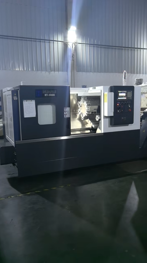
Machinists often notice that a perfectly dialed-in setup starts producing slightly off-size parts after an hour of continuous cutting. The culprit is rarely the tool wearing down—it's the machine frame, spindle, and even the workpiece expanding as temperatures climb. A 5°C rise in a cast iron bed can shift the tool tip by several microns, enough to scrap a tight-tolerance batch. Ignoring thermal drift means chasing dimensional errors that appear random but actually follow a predictable thermal curve.
One practical fix is to give the machine a warm-up cycle before running critical parts. Let the spindle run at moderate speed for 15–20 minutes while circulating coolant through the headstock and ball screws; this stabilizes internal temperature gradients. Another approach is to mount temperature sensors on the column and spindle nose, then use the CNC controller to apply a real-time offset that counteracts measured growth. For machines without this option, simply moving the coolant tank away from the machine base and adding an air chiller to the enclosure can reduce ambient heat input by 30–40%.
Material choice also plays a role. Replacing steel toolholders with carbon fiber or Invar models cuts thermal expansion at the interface by a factor of three or more. On the workpiece side, clamping parts with low thermal mass—like aluminum fixtures instead of solid steel blocks—lets heat dissipate faster and keeps the part at a more uniform temperature during long cutting passes. Finally, scheduling the most demanding cuts early in the shift, before the shop itself heats up, avoids compounding drift from external temperature swings.
Toolpath Tricks for a Mirror Finish on Hardened Steel
The biggest mistake when chasing a mirror finish on hardened steel is assuming the toolpath is just a matter of smaller stepovers. On 58–62 HRC stock, a conventional parallel finish pass tends to leave visible cusps where the tool transitions from climbing to conventional cuts, especially on shallow or steep areas. Instead, switch to a constant-scallop or 3D offset strategy that keeps the ball nose engaged at a consistent angle. This eliminates sudden changes in cutting force that cause micro-chatter and the hazy bands machinists often blame on spindle runout. I’ve seen the same tool, same rpm, and same feed produce a noticeably cleaner surface simply by changing from zig-zag parallel to a single-direction offset path.
Stepover numbers that work in aluminum will destroy the surface finish on hardened steel. A ball endmill should be run with a radial engagement of no more than 2–4% of the tool diameter when finishing hardened material. For a 1/8-inch cutter, that means a stepover of 0.0005 to 0.001 inch. It sounds painfully slow, but the alternative is leaving a crosshatch of tiny ridges that show up under good lighting. Climb milling is non-negotiable, and tilting the tool 5–10 degrees away from vertical keeps the center point from rubbing—that rubbing is what burnishes the surface unevenly and creates the dull gray patches. Keep the feed per tooth consistent; don’t let the controller slow down for corners or small radii.
Entry and exit moves are another overlooked factor. Hardened steel punishes any sudden interruption in tool pressure, so avoid lifting the tool at the end of each pass and plunging back down for the next. Use a helical or ramp lead-in that merges smoothly with the finishing path, and if your CAM allows, blend adjacent passes with a short tangential arc rather than a sharp 90-degree turn. Running all finishing passes in the same direction—rather than back-and-forth—also gives a more uniform lay, which matters if the part will be polished or inspected under a microscope. Some shops even program a tiny overlap of 0.002–0.003 inch between passes to level out any deflection differences from one side of the tool to the other.
Hard Turning Parameters That Skip the Grinding Step
Achieving a grind-free finish on hardened parts comes down to pushing CBN inserts past conventional turning speeds while keeping the depth of cut intentionally shallow. Speeds in the 150 to 220 m/min range, paired with a feed of 0.08 to 0.12 mm/rev, generate enough heat to soften the workpiece surface locally but not enough to destroy the tool edge. The result is a burnished-looking surface that often lands below Ra 0.4 µm, making a follow-up grinder unnecessary.
Tool geometry matters just as much as the numbers on the controller. A wiper insert with a negative rake and a small nose radius spreads cutting pressure evenly, suppressing chatter even when the depth of cut is only 0.1 to 0.3 mm. Combined with a rigid tool holder and a machine spindle that holds runout under 3 microns, these parameters let a single pass hold tolerances tight enough to ship directly after hard turning.
In-Process Gauging Closes the Loop on Variation
In-process gauging doesn't wait for a finished part to drift out of tolerance. It checks critical dimensions between cuts, sometimes even during the cut, using touch probes, laser scanners, or air gauges mounted right on the machine. When a bore starts running a few microns large because a tool edge has worn, the control adjusts the next pass or swaps in a fresh tool. That feedback loop runs continuously, so variation gets corrected before it can stack up into scrap.
The real payback shows up on long runs and tight-tolerance work. Thermal growth in the machine, inconsistent stock allowance, or dull inserts can push a process off center over time. In-process gauging catches those shifts as they happen, applying small offsets instead of letting the process drift until an alarm stops everything. The result is a tighter spread in the data — less deviation, fewer sort-outs, and a process that stays predictable hour after hour.
Operators also stop chasing parts with manual checks. Instead of measuring after every cycle and hand-entering offsets, the machine reads its own work and reacts. That cuts lag time between detecting drift and fixing it. For shops running high-mix or low-volume work, this closed-loop approach keeps each setup from turning into a guessing game, because the machine learns the process behavior and adjusts to hold the target.
One Setup Six Sides Zero Stack Up
Most multi-sided machining jobs force you to reposition the workpiece over and over, each cycle adding a fresh chance for misalignment. Here, a single clamping holds the part steady while every accessible face gets addressed in one continuous pass. No re-indicating, no flipping back and forth, no chasing your own reference points.
That means all six faces—top, bottom, and the four side walls—are finished within the same setup envelope. You don't have to stack separate fixtures or juggle multiple vises to expose different surfaces. The machine simply indexes around the part, keeping the datum intact for every cut.
And because the part never leaves that original reference plane, you eliminate tolerance creep from repeated re-clamping. The result is a geometry that holds true from corner to corner, with no cumulative error and no need to shim or adjust between operations.
FAQ
Thermal drift can quietly ruin a batch before you even measure it. Machines with symmetric headstock designs, active cooling on the spindle and ball screws, plus warm-up cycles that mirror real cutting conditions keep growth predictable and small enough to stay within a few microns.
By pairing high-resolution linear scales with look-ahead servo tuning, the axis motion stays smooth even during sharp direction changes. Some shops also use variable flute end mills or polycrystalline diamond inserts to reduce built-up edge, which directly influences the final Ra.
Horsepower gets the chip off, but damping determines how clean the cut is. Polymer composite bases, tuned mass dampers in the tool post, and rigid box-way construction absorb chatter before it reaches the part. This matters most on long, slender workpieces where overhang amplifies any oscillation.
Look for a spindle with ceramic hybrid bearings, an HSK or Capto interface to minimize runout stack-up, and a chiller that holds bearing temperature within a degree or two. Runout below a micron at the tool taper is a practical benchmark, not just a catalog claim.
On higher-end turning centers, touch probes or laser micrometers feed data back to the control, which nudges tool offsets after each pass. It's not just pass or fail sorting; it can hold a diameter to plus or minus two microns over a full shift as inserts wear, as long as the probing routine is calibrated against a known master.
High-pressure through-tool coolant doesn't just clear chips; it prevents recutting and stabilizes the temperature at the cutting zone. Aimed properly, it can also break the chip into small segments that don't scratch the finished surface on the way out. Emulsion concentration and filtration matter just as much as pressure.
With a climate-controlled room, balanced tooling, and a well-maintained machine, holding plus or minus 0.002 mm on diameter is achievable. Going beyond that usually demands specialized air-bearing spindles, active error compensation, and a process that doesn't rely on a single setup. The machine is only one part of the tolerance stack.
Conclusion
Hitting a true 5-micron tolerance on a turned part rarely comes down to one magic setting. It starts at the spindle. Runout of even 0.003 mm gets multiplied at the tool tip, so shops serious about precision will chase spindle nose TIR before touching offsets. Next comes thermal growth. A machine that warms up unevenly will drift all day, no matter how carefully the first piece was dialed in. Production cells counter this with warm-up cycles, chiller-controlled ballscrews, and sometimes glass scales placed close to the cutting zone. The payoff is predictable size from morning to afternoon without constant offset tweaks.
Once the machine is stable, the toolpath and cutting parameters take over. On hardened steels above 50 HRC, light finishing passes with a small nose radius and a wiper insert can produce a near-ground finish without a grinder—if the speed and feed stay inside a narrow window. Adding in-process gauging closes the loop: probes or scanning heads measure the actual diameter while the part is still chucked, and the control updates offsets automatically. Pair that with a multi-axis turning center that mills, drills, and turns all six sides in one chucking, and stack-up errors between features practically disappear. Nothing about this is exotic; it is just a disciplined combination of spindle health, thermal control, aggressive hard turning parameters, and closed-loop measurement.
Contact Us
Contact Person: Tim
Email: [email protected]
Tel/WhatsApp: +86 15522553731
Website: https://www.winnrui-cnc.com/